Aluminum Extrusion Process
Extrusion is defined as the process of shaping material, such as aluminum, by forcing it to flow through a shaped opening in a die. Extruded material emerges as an elongated piece with the same profile as the die opening.
To aid in understanding the aluminum extrusion process think about a Play-Doh® Fun Factory and how it works. Think of the Fun Factory as the extrusion press, the handle as the ram, the shape bar as the die, and the Play-Doh® as the aluminum billet. The first step is to choose the desired shape and color. Think of the shape as the die and the color as the temper and alloy needed. Next, the Play-Doh® is inserted into the holding chamber and pressure is applied to the handle, which forces Play-Doh® through the shape. In an extrusion press, pressure is applied to the billet by the ram where the dummy block is attached to the end of the ram stem. When Play-Doh® begins to emerge, it has effectively been "extruded". The same principles apply to extrusions from aluminum billets but considerably more detailed and sophisticated technologies are involved.
Press size determines how large of an extrusion can be produced. Extrusion size is measured by its longest cross-sectional dimension, i.e. its fit within a circumscribing circle. A circumscribed circle is the smallest circle that will completely enclose the cross section of an extruded shape.
The most important factor to remember in the extrusion process is temperature. Temperature is most critical because it gives aluminum its desired characteristics such as hardness and finish.
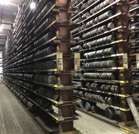
STEPS IN THE ALUMINUM EXTRUSION PROCESS
-
- Billets must be heated to approximately 800-925° F.
- After a billet reaches the desired temperature, it is transferred to the loader where a thin film of smut or lubricant is added to the billet and to the ram. The smut acts as a parting agent (lubricant) which keeps the two parts from sticking together.
- The billet is transferred to the cradle.
- The ram applies pressure to the dummy block which, in turn, pushes the billet until it is inside the container.
- Under pressure the billet is crushed against the die, becoming shorter and wider until it has full contact with the container walls. While the aluminum is pushed through the die, liquid nitrogen flows around some sections of the die to cool it. This increases the life of the die and creates an inert atmosphere which keeps oxides from forming on the shape being extruded. In some cases nitrogen gas is used in place of liquid nitrogen. Nitrogen gas does not cool the die but does create an inert atmosphere.
- As a result of the pressure added to the billet, the soft but solid metal begins to squeeze through the die opening.
- As an extrusion exits the press, the temperature is taken with a True Temperature Technology (3T) instrument mounted on the press platen. The 3T records exit temperature of the aluminum extrusion. The main purpose of knowing the temperature is to maintain maximum press speeds. The target exit temperature for an extrusion is dependent upon the alloy. For example, the target exit temperature for the alloys 6063, 6463, 6063A, and 6101 is 930° F (minimum). The target exit temperature for the alloys 6005A, and 6061 is 950° F (minimum).
- Extrusions are pushed out of the die to the leadout table and the puller, which guides metal down the run-out table during extrusion. While being pulled, the extrusion is cooled by a series of fans along the entire length of the run-out and cooling table. (Note: Alloy 6061 is water quenched as well as air quenched.)

- Not all of the billet can be used. The remainder (butt) contains oxides from the billet skin. The butt is sheared off and discarded while another billet is loaded and welded to a previously loaded billet and the extrusion process continues.
- When the extrusion reaches a desired length, the extrusion is cut with a profile saw or a shear.
- Metal is transferred (via belt or walking beams systems) from the run-out table to the cooling table.
- After the aluminum has cooled and moved along the cooling table, it is then moved to the stretcher. Stretching straightens the extrusions and performs 'work hardening' (molecular re-alignment which gives aluminum increased hardness and improved strength).
- The next step is sawing. After extrusions have been stretched they are transferred to a saw table and cut to specific lengths. The cutting tolerance on saws is 1/8 inch or greater, depending on saw length.
After the parts have been cut, they are loaded on a transportation device and moved into age ovens. Heat-treating or artificial aging hardens the metal by speeding the aging process in a controlled temperature environment for a set amount of time.
-
PARTS OF THE PRESS
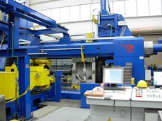
Understanding how an extrusion press works requires identifying the press parts and explaining their use. An extrusion press is made up of a front platen and back platen held together by four tie rods. The parts of the press that actually make the extrusion are as follows:
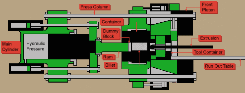
Main Cylinder- Chamber and cylinder of an extrusion press into which hydraulic fluid is pumped to generate the desired ram pressure and movement.
Hydraulic Pressure- Pressure used to move the ram forward at the required Pounds per Square Inch.
Ram- A steel rod attached to the main cylinder with a dummy block on the end that enters the container and applies pressure to the billet.
Dummy Block- A tight fitting steel block attached to the ram stem on a press which seals the billet in the container and prevents metal from leaking backward.
Billet- Aluminum log cut to specific lengths which are fed into the press as extrusion materials.
Container- Chamber in an extrusion press which holds the billet as it is pushed through a die at one end while under pressure from a dummy block and ram entering at the other end. The container resides in the container housing. All containers are lined with a liner which holds the billet in place while it is being extruded.
Tool Stack (Die Assembly) - solid: die ring, die, backer, bolster, and sub-bolster (Sub-bolsters are not used in Carthage or Newnan). Hollow: die ring, die mandrel, die cap, bolster, sub-bolster
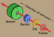
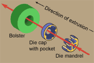
Die Holder- Container of the tool stack.
Die Lock- Locks the die into the die holder.
Log Oven/ Billet Oven- Press component used to heat the logs/ billets to extrusion temperature. Presses equipped with log shears have log ovens; others have billet ovens.
Log Shear- Used for cutting logs to desired billet lengths (only on presses with log ovens).
Butt Shear- Shears off the unextruded portion of the billet (butt) remaining in the container after the extrusion cycle is completed. The butt is where oxides are located after the ram has pushed the billet through the container.
Die Oven- Oven where dies are heated to 750° - 900° F for 4-6 hours before being used.
Cradle- holds the billet while it is being pushed into the extrusion press by the pressure from the ram.
Press Leadout Table- Table which supports extrusion between the die and run out table.
Run Out Table- Table at immediate exit of press leadout equipment which helps guide and support extrusions.
Back/Front Press Platen- The extrusion press consists of these two sections.
Tie Rods- Connects the back and front press platen.
Canister- used to help guide the aluminum extrusions from the die. It has the same number of holes as the die itself and can be used on all presses. Newnan is moving away from using them because they are costly and hard to handle.
Platen Pressure Ring- A hardened tool steel ring inserted into the platen to support the die stack. Pressure applied by the main cylinder to the ring causes stress and wear resulting in a need for periodic replacement.
DIRECT & INDIRECT EXTRUSION
There are two types of extrusion processes, direct and indirect. Direct extrusion is a process in which the die head is held stationary and a moving ram forces the metal through it. Indirect extrusion is a process in which the billet remains stationary while the die assembly located on the end of the ram, moves against the billet creating pressure needed for metal to flow through the die.
TEMPER
Temper is the combination of aluminum hardness and strength produced by mechanical and/or thermal treatments.
The measures used to test mechanical properties of aluminum are tensile, yield, and elongation. Tensile is an indication of the maximum pulling load that a material can stand without failure, usually measured in pounds per square inch of cross-sectional area. Yield is the stress at which a material first exhibits a specific permanent set. Elongation is the maximum percentage of stretch a material will stand before breaking. A defined range of alloy and temper properties must be met in order to satisfy certificate of compliance requirements.
Rockwell Hardness is an indentation hardness test based on the penetration depth of a specified penetrator into a specimen under certain fixed conditions.
Webster is a relative indicator of hardness but does not guarantee certificate of compliance requirements.
FACTORS AFFECTING EXTRUSION
Shape is a determining factor in the part's cost and ease with which it can be extruded. In extrusion a wide variety of shapes can be extruded, but there are limiting factors to be considered. These include size, shape, alloy, extrusion ratio, tongue ratio, tolerance, finish, factor, and scrap ratio. If a part is beyond the limits of these factors, it cannot be extruded successfully.
The size, shape, alloy, extrusion ratio, tongue ratio, tolerance, finish, and scrap ratio are interrelated in the extrusion process as are extrusion speed, temperature of the billet, extrusion pressure and the alloy being extruded.
In general, extrusion speed varies directly with metal temperature and pressure developed within the container. Temperature and pressure are limited by the alloy used and the shape being extruded. For example, lower extrusion temperatures will usually produce shapes with better quality surfaces and more accurate dimensions. Lower temperatures require higher pressures. Sometimes, because of pressure limitations, a point is reached where it is impossible to extrude a shape through a given press.
The preferred billet temperature is that which provides acceptable surface and tolerance conditions and, at the same time, allows the shortest possible cycle time. The ideal is billet extrusion at the lowest temperature which the process will permit. An exception to this is the so-called press-quench alloys, most of which are in the 6000 series. With these alloys, solution heat-treat temperatures within a range of 930°-980° F must be attained at the die exit to develop optimum mechanical properties.
At excessively high billet temperatures and extrusion speeds, metal flow becomes more fluid. The metal, seeking the path of least resistance, tends to fill the larger voids in the die face, and resists entry into constricted areas. Under those conditions, shape dimensions tend to fall below allowable tolerances, particularly those of thin projections or ribs.
Another result of excessive extrusion temperatures and speeds is tearing of metal at thin edges or sharp corners. This results from the metal's decrease in tensile strength at excessively high-generated temperatures. At such speeds and temperatures, contact between the metal and the die bearing surfaces is likely to be incomplete and uneven, and any tendency toward waves and twists in the shape is intensified.
As a rule, an alloy's higher mechanical properties means a lower extrusion rate. Greater friction between the billet and the liner wall results in a longer time required to start the billet extruding. The extrusion ratio of a shape is a clear indication of the amount of mechanical working that will occur as the shape is extruded.
Extrusion Ratio = area of billet/area of shape.
When the extrusion ratio of a section is low, portions of the shape involving the largest mass of metal will have little mechanical work performed on it. This is particularly true on approximately the first ten feet of extruded metal. Its metallurgical structure will approach the as-cast (coarse grain) condition. This structure is mechanically weak and shapes with an extrusion ratio of less than 10:1 may not be guaranteed as to mechanical properties.
As might be expected, the situation is opposite when the extrusion ratio is high. Greater pressure is required to force metal through the smaller openings in the die and extreme mechanical working will occur. Normally acceptable extrusion ratios for hard alloys are limited to 35:1 and for soft alloys, it is 100:1. The normal extrusion ratio range for hard alloys is from 10:1 to 35:1, and for soft alloys is 10:1 to 100:1. These limits should not be considered absolute since the actual shape of the extrusion can affect results. The higher the extrusion ratio, the harder the part is to extrude which is the result of the increased resistance to metal flow. Hard alloys require maximum pressure for extrusion and are even more difficult because of their poor surface characteristics which demand the lowest possible billet temperature.
Difficulty factor is also used to determine a part's extrusion performance.
Factor = Perimeter of Shape/ Weight per Foot.
Weight per foot is of primary importance because of the consideration for profitable press operation. As might seem obvious, a lighter section normally requires a smaller press to extrude it. However, other factors may demand a press of greater capacity such as a large, thin wall hollow shape. Though it has low weight per foot it may take more press tonnage to extrude it. The same reasoning applies to the factor as with the extrusion ratio. A higher factor makes the part more difficult to extrude consequently affecting press production.
The tongue ratio also plays an important role in determining a part's extrusion performance. The tongue ratio of an extrusion is determined as follows: square the smallest opening to the void, calculate the total area of the shape, and then divide the opening squared by the area.. The higher the ratio, the more difficult the part will be to extrude.
In order to help us understand your needs and requirements and service you better, the following is a check list of things to consider when submitting items to an extruder for quoting or new business:
- Description or drawings of the part- talk to the extruder early before the design is finalized.
- Specifications to be met; Federal specs, military, ASTM, etc.
- Alloy and temper; if unknown, indicate requirements for strength, corrosion resistance, machinability, finish, weldability, to aid the extruder in making a recommendation.
- End use length and purchase length.
- Tolerances; commercial, per drawing, other.
- Surface Finish; mill, anodize, paint, exposed surfaces, etc.
- Packaging; acceptable maximum and minimum weight per package and shipping and handling requirements.
- Secondary fabrication requirements-mitering, punching, bending, anodizing, drilling, etc.
- Product end-use.
- Quantity needed; this order and on an annual basis.
- Shipping date.
- Special quality considerations.
