
Designing Aluminum Extrusions
SHAPE CONFIGURATION
One of the major advantages of aluminum extrusions is that they can be designed in virtually any shape that meets the designer's structural and aesthetic requirements. They can be designed to aid in assembly, reduce or eliminate forming or welding operations, reduce machining requirements, and many other purposes.
There are three general classifications of extruded shapes: solid, semihollow, and hollow.
HOLLOW SHAPES
A hollow shape is a shape which completely encloses a void anywhere in its cross-section. Hollow shapes are sub-divided into three different classes.
Class 1 hollow shapes
There are three requirements for a shape to be classified as a Class 1 hollow:
- The internal void is round
- The void is one inch or more in diameter
- The shape is symmetrically balanced around the void by two or more axes
Class 2 hollow shapes
There are three different requirements for a shape to be classified as a Class 2 hollow:
- The shape is not a Class 1 hollow
- It has a single void no smaller than 0.375 inches in diameter or 0.110 square inches in area
- The entire shape fits within a 5 inch circumscribing circle
Class 3 hollow shapes
A Class 3 hollow is any hollow shape that cannot be classified as Class 1 or Class 2. For example, a shape with multiple voids would be a Class 3 hollow.
SEMIHOLLOW SHAPES
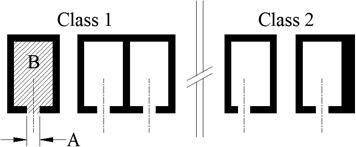
A semihollow shape is one that partially encloses a void. If the void or voids are symmetrical about the centerline of the gap, the semihollow is classified as a Class 1 semihollow. If the void is not symmetrical about the centerline of the gap, or the wall thicknesses on either side differ, then the semihollow is classified as a Class 2 semihollow.
The actual determination that a shape is a semihollow is made by calculating the gap ratio: the area of the partially enclosed void, B, divided by the square of the gap, A. Once you have determined the class and gap ratio, use the following table to determine if the shape is in fact a semihollow. If the table does indicate the shape is a semihollow, then it is a solid.
Note: the following table is appropriate for use with 6000 series alloys.
| Gap Width (inches) | Class 1 | Class 2 |
|---|---|---|
| 0.040 - 0.062 | 2.0 | 2.0 |
| 0.063 - 0.124 | 3.0 | 2.5 |
| 0.125 - 0.249 | 3.5 | 3.0 |
| 0.250 - 0.499 | 4.0 | 3.5 |
| 0.500 - 0.999 | 4.0 | 3.5 |
| 1.000 - 14.999 | 3.5 | 3.0 |
| 2.000 and over | 3.0 | 3.0 |
SOLID SHAPES
A solid shape is any shape that is not a hollow or a semihollow.
SURFACE FINISH
Aluminum extrusions can be provided with a variety of finishes (see our Capabilities page for a list of finishes we offer). However, since aluminum is a soft metal, it is not not uncommon for surfaces to become marred during processing. If a product has surfaces that are exposed during use, where processing marks would be objectionable, special care must be taken to provide an acceptable surface. Customers should consult with Bonnell Aluminum's Design Engineering group so that we can design the dies and select appropriate packaging to protect critical exposed surfaces.
TOLERANCES
In applications where an extrusion is designed to minimize machining or to mate with another extrusion in any manner, standard dimensional tolerances can become critical. The Aluminum Association publishes standard tolerance charts which cover such things as metal dimensions, space dimensions, straightness, twist, flatness and more. If you need help interpreting these tables, or if you believe your application requires tighter than standard tolerances, please contact Bonnell Aluminum's Design Engineering department for assistance.
ALLOY SELECTION
Alloy and Temper selection is typically influenced by the mechanical properties required for a given application. For example, 6063 alloy is typically used in moderate stress applications. 6061 alloy is typically used in structural applications as it has higher mechanical properties than 6063.
The major alloying elements of the 6000 series alloys are magnesium and silicon. The 6000 series is the most popular alloy class and is used in roughly 75% of extrusion applications. It is heat treatable and offers good strength, corrosion resistance, formability, machinability and weldability.
Chemical Composition of Extrusion Alloys available from Bonnell Aluminum
| Alloy | Si | Fe | Cu | Mn | Mg | Cr | Zn | Ti | Others Each/Total | Al |
|---|---|---|---|---|---|---|---|---|---|---|
| 6005 | 0.60-0.90 | 0.35 | 0.10 | 0.10 | 0.40-0.60 | 0.10 | 0.10 | 0.10 | 0.05/0.15 | remainder |
| 6005A* | 0.50-0.90 | 0.35 | 0.30 | 0.50 | 0.40-0.70 | 0.30 | 0.20 | 0.10 | 0.05/0.15 | remainder |
| 6060 | 0.30-0.60 | 0.10-0.30 | 0.10 | 0.10 | 0.35-0.60 | 0.05 | 0.15 | 0.10 | 0.05/0.15 | remainder |
| 6061 | 0.40-0.80 | 0.70 | 0.15-0.40 | 0.15 | 0.80-1.20 | 0.04-0.35 | 0.25 | 0.15 | 0.05/0.15 | remainder |
| 6063 | 0.20-0.60 | 0.35 | 0.10 | 0.10 | 0.45-0.90 | 0.10 | 0.10 | 0.10 | 0.05/0.15 | remainder |
| 6082 | 0.70-1.30 | 0.50 | 0.10 | 0.40-1.00 | 0.60-1.20 | 0.25 | 0.20 | 0.10 | 0.05/0.15 | remainder |
| 6105 | 0.60-1.00 | 0.35 | 0.10 | 0.10 | 0.45-0.80 | 0.10 | 0.10 | 0.10 | 0.05/0.15 | remainder |
| 6351 | 0.70-1.30 | 0.50 | 0.10 | 0.40-0.80 | 0.40-0.80 | 0.20 | 0.20 | 0.05/0.15 | remainder | |
| 6463 | 0.20-0.60 | 0.15 | 0.20 | 0.05 | 0.45-0.90 | 0.05 | 0.05/0.15 | remainder |
*Manganese plus chromium must be between 0.12-0.50%
The temper designations that apply to 6000 series alloys are: O, annealed and T, thermally treated to produce stable tempers. Typical tempers include:
- O - fully annealed (lowest strength temper)
- T1 - cooled from an elevated temperature and naturally aged
- T4 - solution heat treated and naturally aged
- T5 - cooled from an elevated temperature and artificially aged
- T6 - solution heat treated and artificially aged
Mechanical Properties of Extrusion Alloys available from Bonnell Aluminum
Alloy |
Temper | Wall Thickness Inches (min.) |
Tensile Strength - ksi | Elongation % (min.) 2in or 4D |
|
|---|---|---|---|---|---|
| Ultimate (min.) |
Yield - 0.2% offset (min.) |
||||
| 6005 | -T1 | Up thru 0.500 | 25.0 | 15.0 | 16 |
| -T5 | Up thru 0.124 0.125 |
38.0 38.0 |
35.0 35.0 |
8 10 |
|
| 6005A | -T1 | Up thru 0.249 | 25.0 | 14.5 | 15 |
| -T5 | Up thru 0.249 0.250-0.999 |
38.0 38.0 |
31.0 31.0 |
7 9 |
|
| -T61 | Up thru 0.249 0.250-1.000 |
38.0 38.0 |
35.0 35.0 |
8 10 |
|
| 6060 | -T1 | Up thru 0.500 0.501-1.000 |
17.0 16.0 |
9.0 8.0 |
12 12 |
| -T4 | Up thru 0.500 0.501-1.000 |
19.0 18.0 |
10.0 9.0 |
14 14 |
|
| -T5 | Up thru 0.500 0.501-1.000 |
22.0 21.0 |
16.0 15.0 |
8 8 |
|
| -T6 | Up thru 0.124 0.125-1.000 |
30.0 30.0 |
25.0 25.0 |
8 10 |
|
| 6061 | -T4 | All | 26.0 | 16.0 | 16 |
| -T5 | Up thru 0.625 | 35.0 | 30.0 | 8 | |
| -T6 and T6511 |
Up thru 0.249 0.250 and over |
38.0 38.0 |
35.0 35.0 |
8 10 |
|
| 6063 | -T1 | Up thru 0.500 0.501-1.000 |
17.0 16.0 |
9.0 8.0 |
12 12 |
| -T4 | Up thru 0.500 0.501-1.000 |
19.0 18.0 |
10.0 9.0 |
14 14 |
|
| -T5 | Up thru 0.500 0.501-1.000 |
22.0 21.0 |
16.0 15.0 |
8 8 |
|
| -T52 | Up thru 1.000 | 22.0 (30.0 max.) | 16.0 (25.0 max.) | 8 | |
| -T6 | Up thru 0.124 0.125-1.000 |
30.0 30.0 |
25.0 25.0 |
8 10 |
|
| 6082 | -T6 and T6511 |
0.200 - 0.750 0.751 - 6.000 6.001 - 8.000 |
45.0 45.0 41.0 |
38.0 38.0 35.0 |
6 8 6 |
| 6105 | -T1 | 0.500 max. | 25.0 | 15.0 | 16 |
| -T5 | 0.500 max. | 38.0 | 35.0 | 8 | |
| 6351 | -T4 | Up thru 0.749 | 32.0 | 19.0 | 16 |
| -T5 | Up thru 0.249 0.250 - 1.000 |
38.0 38.0 |
35.0 35.0 |
8 10 |
|
| -T6 | Up thru 0.124 0.125 - 0.749 |
42.0 42.0 |
37.0 37.0 |
8 10 |
|
| 6463 | -T1 | Up thru 0.500 | 17.0 | 9.0 | 12 |
| -T4 | Up thru 0.500 0.501-1.000 |
19.0 18.0 |
10.0 9.0 |
14 14 |
|
| -T5 | Up thru 0.500 | 22.0 | 16.0 | 8 | |
| -T6 | Up thru 0.124 .125-0.500 |
30.0 30.0 |
25.0 25.0 |
8 10 |
|
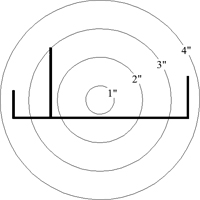
CIRCUMSCRIBING CIRCLE SIZE & DIE DIFFICULTY
One measurement of the size of an extrusion is the diameter of the smallest circle that will completely enclose the extrusion's cross-section. This is know in the extrusion industry as the circumscribing circle, or cc. In the figure shown to the right, the extrusion would be classified as having a 3-4" cc. With the installation of our 5500 ton extrusion press in 2009, Bonnell Aluminum can extrude architectural quality extrusions with circumscribing circles in excess of 16 inches.
The figure at right is also helpful in visualizing an extrusion die. The extrusion is produced by cutting the shape out of a piece of steel, then forcing the aluminum through it under pressure. The perimeter of the shape is where the aluminum comes in contact with the steel producing friction. The die difficulty factor is determined by dividing the area of the extrusion by the total perimeter. The higher the factor, the more difficult it is to get the aluminum to "break out" through the die.
WALL THICKNESS
It is generally desirable from a cost standpoint to specify the minimum metal thickness that will meet the structural requirements of a profile. One of the advantages of aluminum extrusions is that extra metal can be added where it is needed and removed where it is not. However, large differences between adjacent wall thicknesses can cause uneven conditions during extrusion and cooling which may make it difficult to hold the desired dimensions. Adjacent wall thickness ratios greater than 2-1 should be avoided and wherever wall of different thickness meet, the transition should use rounded corners to ease the flow of metal are reduce streaks on the opposite surface. The following reference chart shows the minimum wall thicknesses practical from an extrusion standpoint based on the profile's circle size.
Minimum Wall Thickness Reference Chart
| Circumscribing Cirle (inches) | Solids & Semihollows | Class 2 Hollows |
|---|---|---|
| 0.5 to (not incl) 2 | 0.040 | 0.055 |
| 2 to (not incl) 3 | 0.045 | 0.062 |
| 3 to (not incl) 4 | 0.050 | 0.078 |
| 4 to (not incl) 5 | 0.062 | 0.094 |
| 5 to (not incl) 6 | 0.078 | 0.110 |
| 6 to (not incl) 7 | 0.094 | 0.125 |
| 7 to (not incl) 8 | 0.110 | 0.140 |
| 8 to (not incl) 9 | 0.125 | 0.156 |
| 9 to (not incl) 10 | 0.140 | 0.188 |
| 10 to (not incl) 11 | 0.156 | 0.204 |
| 11 to (not incl) 12 | 0.172 | 0.220 |
| 12 to (not incl) 13 | 0.188 | 0.236 |
| 13 to (not incl) 16 | Subject to inquiry | Subject to inquiry |
Standard Screw Slots
| Self Tapping Screw Type F | ||
|---|---|---|
| NC | NF | Slot Diameter |
| 4 - 40 | 4 - 48 | 0.099 ± 0.006 |
| 6 - 32 | 6 - 40 | 0.120 ± 0.006 |
| 8 - 32 | 8 - 36 | 0.147 ± 0.006 |
| 10 - 24 | 10 - 32 | 0.169 ± 0.006 |
| 12 - 24 | 12 - 28 | 0.190 ± 0.006 |
| 1/4 - 20 | 1/4 -28 | 0.228 ± 0.006 |
